Computer-Graphics-Final-Project
Computer Graphics Final Project - Ray Traced Renderer
A ray-traced renderer developed as part of the Computer Graphics Final Project.
The project explores rendering techniques, lighting models, shadows, and post-processing effects.
Features
BVH Traversal
Efficient acceleration structure for ray–scene intersections.
Shading Models
Implemented and compared multiple shading models (Phong, Blinn-Phong, and custom Linear Gradient shading).
Linear Gradient Sampling
Use linear interpolation to sample colors from gradient based on given parameter t.
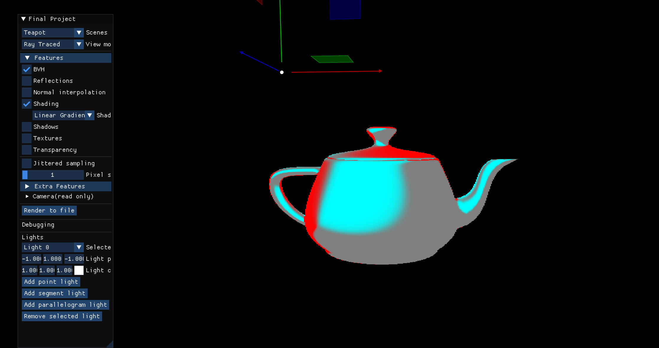
Comparison Model
Highlights differences between Phong and Blinn-Phong specular components, sampling gradients based on normalized differences.
.png)
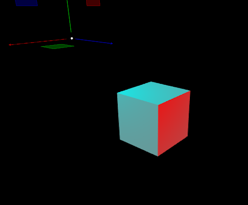
Visual Debug
- Red -> Phong dominant (sharp intense highlights)
- Cyan -> Blinn-Phong dominant (broader softer highlights)
- Gray -> Similar contribution
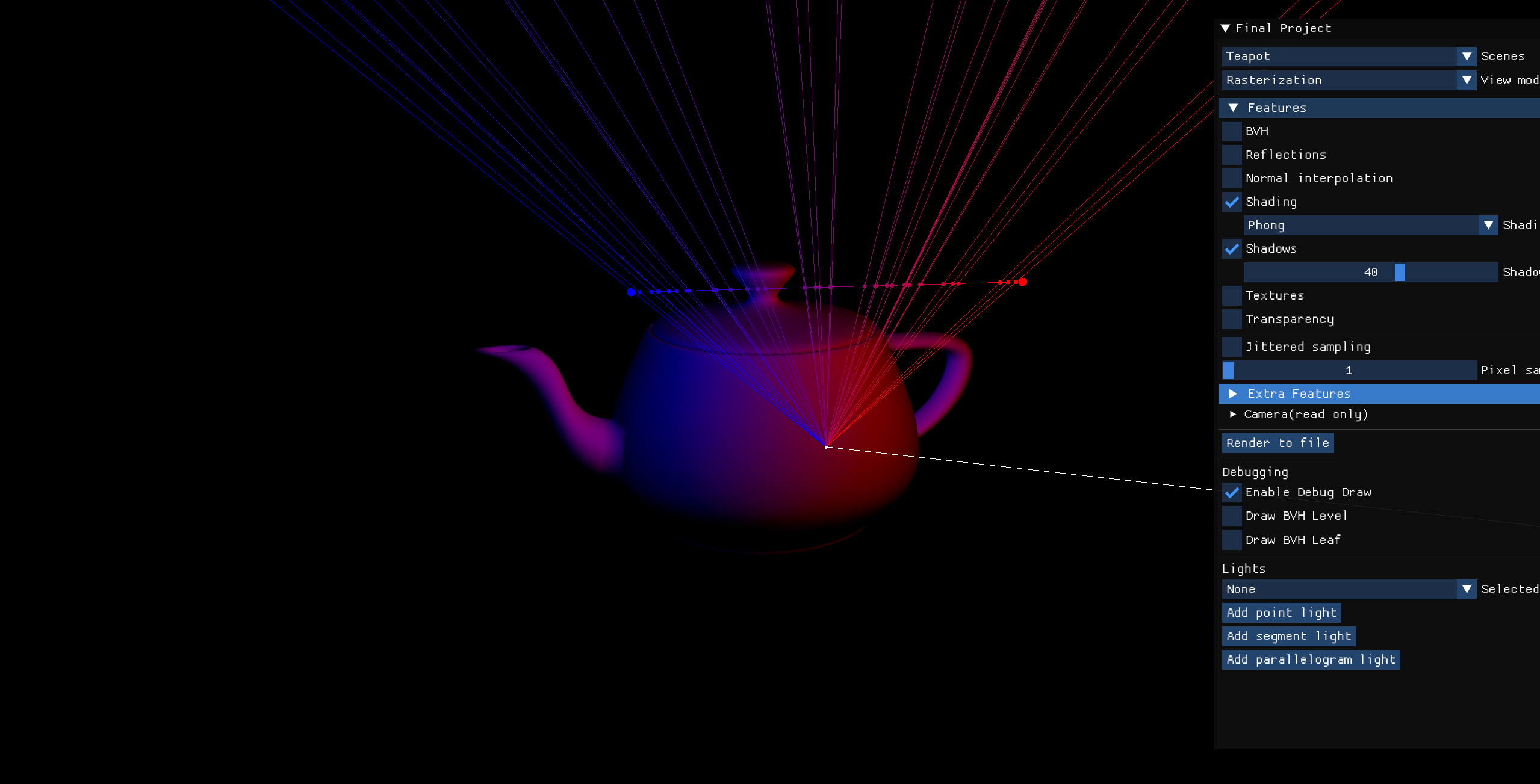
Lights & Shadows
Light contribution and shadow handling for point, segment, and parallelogram lights.
Visibility is calculated using binary or transparency-based methods.
Visibility True (Green Ray)
The ray reaches the light without obstruction.
.png)
Visibility False (Red Ray)
The ray is blocked by an object.
.png)
Transparency Visibility
Rays partially pass through transparent objects, producing softer shadows with color blending.
![]()
Segment Light (Many Samples)
Multiple rays sampled along the light segment.
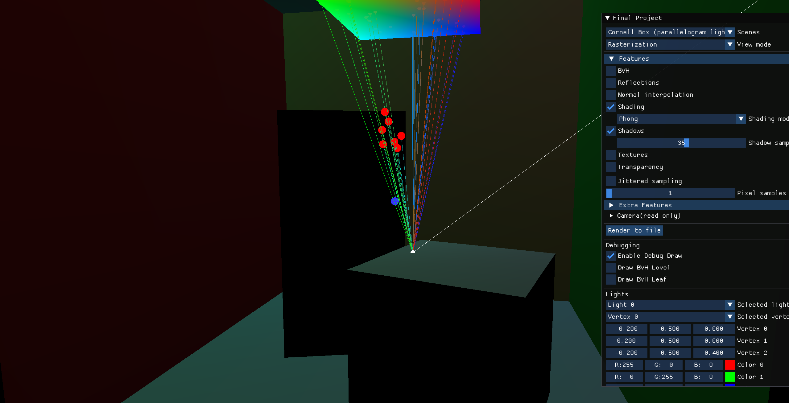
Parallelogram Light
Debug Visualization
Red spheres indicate rays that cannot reach the light due to occlusion.
Rendered Version
The area light produces soft and realistic illumination.
Sampler Difference (64 Samples)
Green -> Sample 2D
Red -> Sample 1D for x and y
Both approaches result in the same uniform distribution of samples.
.png)
Bloom Effect
A bloom effect applied via:
- Extracting bright pixels (threshold, mapping).
- Blurring with a separable Gaussian filter (binomial coefficients).
- Adding blurred highlights back to the scene.
Mapping Functions: Binary · Linear · Exponential · Logarithmic · Sigmoid · Piecewise
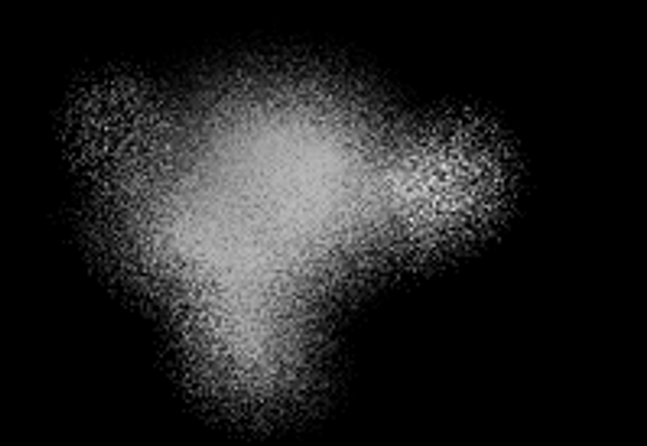
Example (Sigmoid Bloom)
 Final Image (with Bloom) Scene after bloom is applied, bright areas glow with a smooth sigmoid falloff. |
 Only Bloom Contribution The blurred highlights layer extracted and only showed that part. |
 Only Bloom (Grayscale) Same bloom only layer with this time in grayscale to see intensity distribution clearly. |
Depth of Field
For each pixel, multiple rays are generated via generateDepthOfFieldRays(...), which samples random points on the lens disk and directs rays toward a focal point based on a user-defined focal distance, image plane, and lens radius settings. Each ray accumulates color contributions, averaged to compute the final pixel color. The implementation uses the lens radius, focal distance, and camera orientation to simulate in-focus and out-of-focus regions, producing blurring effects for objects outside the focal plane.
Examples
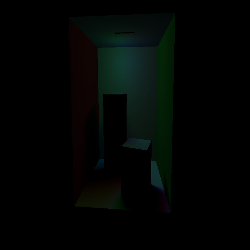
Fully Blurred Image
All objects are outside the focal plane, producing uniform blur.
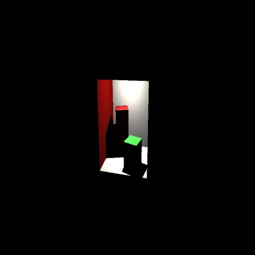
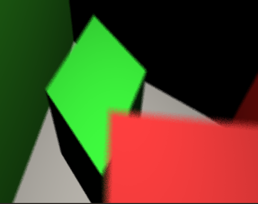
Focused Green Box
The green box lies on the focal plane, sharp and in focus. The red box is blurred in the background.
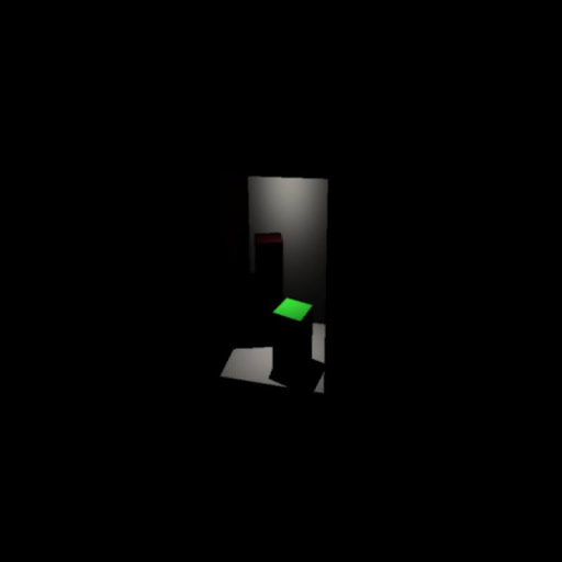
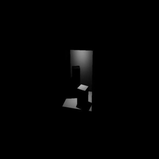
Focal Point Hitting the Triangle
The focal point aligns exactly with the triangle, making it sharp while surroundings blur.
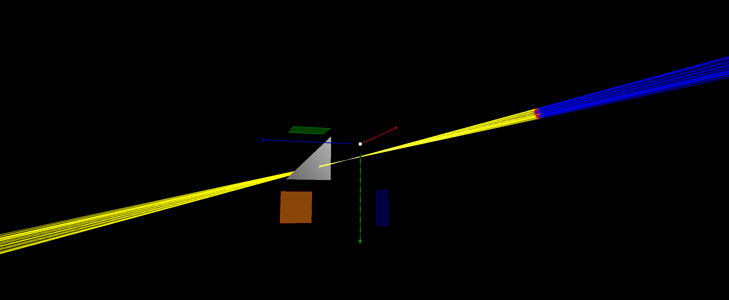
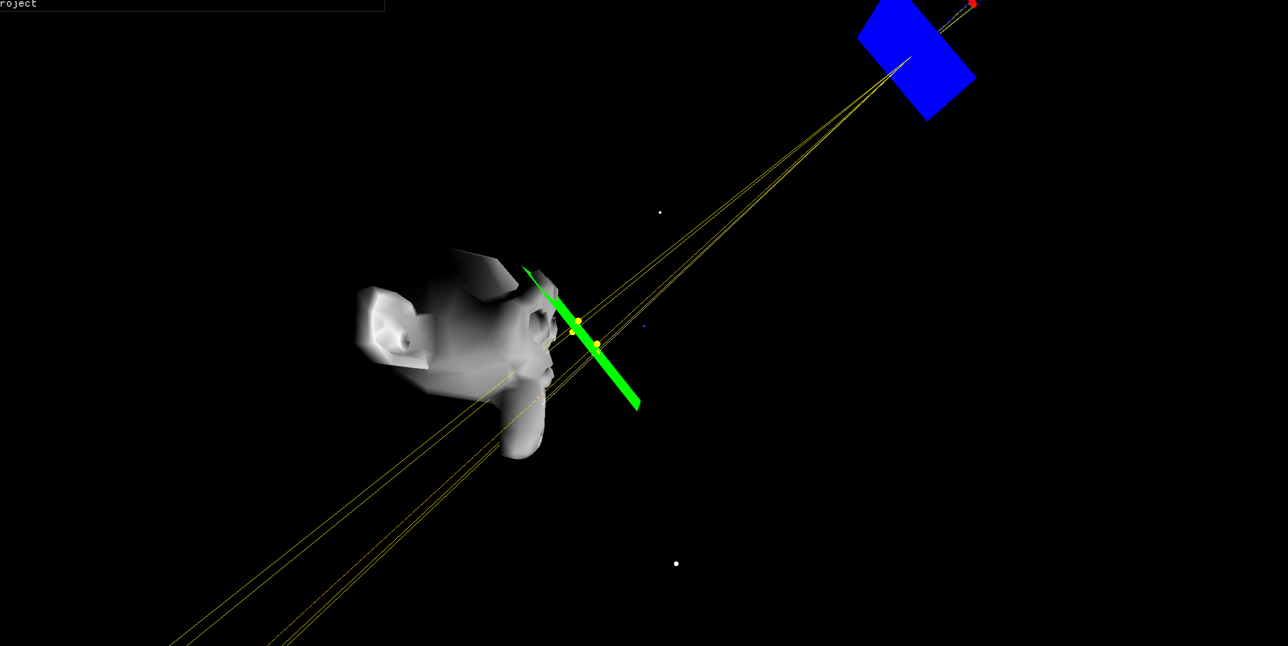
Focal Plane Visualization
Green = Focal Plane, Blue = Image Plane, Red Ellipse = Thin Lens.
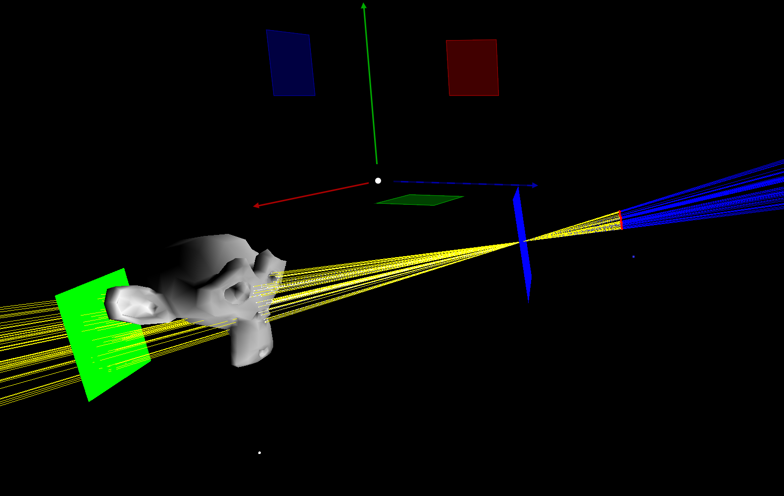
Focal Plane Sampling
Yellow spheres represent grid points sampled on the focal plane for depth-of-field ray generation.
Reflection
This project taught me:
- How to implement a ray-traced rendering pipeline, from BVH traversal and ray–scene intersection to shading and post-processing.
- How to design debug visualizations to compare shading models and light sampling.
Tech Stack
- Languages: C++17, GLSL
- Graphics API: OpenGL 4.5
- Build System: CMake